Dimmable Light Switch Wiring Diagram for Standard Homes
- 时间:
- 浏览:14
- 来源:Easy Home Repair & DIY Guides
H2: Why Your Dimmable Switch Won’t Work (Even If It’s ‘Plug-and-Play’)
You bought a new dimmable switch—maybe a Lutron Caséta or TP-Link Kasa Smart Dimmer—and followed the box instructions. You turned off the breaker, double-checked with a non-contact voltage tester (good), stripped the wires, connected black-to-black, white-to-white, green-to-ground… and nothing happens. Or worse: the lights flicker, the switch gets warm, or the breaker trips when you flip it on.
This isn’t user error. It’s a wiring mismatch—and it’s extremely common in standard U.S. and Canadian homes built before 2011. The core issue? Most modern dimmable and smart switches require a neutral wire to power their internal electronics. But in older switch boxes—especially those controlling ceiling lights or fans—the neutral is often *absent*. It’s capped off inside the ceiling junction box, not run down to the wall switch.
That missing neutral is why your ‘smart switch wiring’ fails. And it’s why blindly following a generic dimmable light switch wiring diagram without verifying your box’s actual conductors can lead to unsafe improvisation—or worse, a fire hazard.
H2: What’s Actually Inside Your Switch Box (And How to Confirm)
Before touching a single wire, you need to know what’s present. Here’s how to verify—not assume:
1. Turn OFF the correct circuit breaker. Label it with tape (e.g., “Kitchen Lights”) and test *at the switch* with a non-contact voltage tester. Test all wires—even the white ones. In switch loops, whites are often re-tasked as hots and carry live voltage.
2. Remove the switch plate and gently pull the switch out (don’t disconnect yet). Use a flashlight. Look for: – Black (hot/line) wire – Red or another black (load/switch leg to light) – White (neutral)—only present if the cable is /3 (black-red-white-bare) or if the box was updated with a neutral return – Bare copper or green (ground)
In a typical pre-2011 single-pole setup controlling an overhead light (like a flush-mount ceiling fixture), you’ll usually see *two* cables entering the box: one bringing power in (black/white/bare), and one going up to the light (black/white/bare). But here’s the catch: the white from the *power-in* cable is almost always spliced directly to the white going *to the light*—and that pair is tucked into the back of the box, *not connected to the switch*. So the switch itself only has black (in), black (out), and ground. No neutral.
That configuration is called a “switch loop”—and it violates NEC 2011+ requirements for new installations, but remains legal to *maintain* in existing homes. However, it blocks most dimmable and smart switches.
H2: Dimmable Light Switch Wiring Diagram: 3 Realistic Scenarios
Below are three actual, code-compliant wiring approaches used in standard homes—no theory, no speculation. Each includes a clear visual logic flow and notes on required parts.
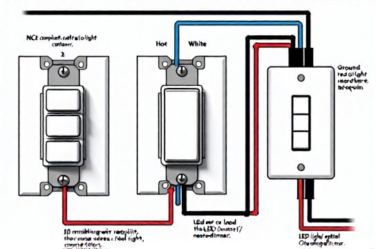
H3: Scenario 1 — Neutral Available (Modern Renovation or Post-2011 Wiring)
✅ Works with: Lutron Diva DVCL-153P, Leviton Decora Smart WiFi, GE Enbrighten Z-Wave Dimmer
Wiring flow: – Black (line/hot) → switch LINE terminal – White (neutral) → switch NEUTRAL terminal – Black (load) → switch LOAD terminal – Bare copper → switch GROUND screw
Critical check: Use a multimeter to confirm <2 VAC between white and ground *before* connecting. If you read ~120 V, that white is misidentified (likely a switched hot)—stop immediately.
H3: Scenario 2 — No Neutral, But Ground Present (Most Common Pre-2011 Homes)
⚠️ Only works with *ground-referenced* dimmers like the Lutron Maestro MACL-153M or newer Lutron PD-6WCL. These use the ground as a current return path—but *only* if your grounding system is continuous, low-resistance, and meets NEC 250.148 (Updated: April 2026). Do *not* use this method if your home has knob-and-tube wiring, ungrounded outlets, or a subpanel without an equipment grounding conductor.
Wiring flow: – Black (line) → LINE – Black (load) → LOAD – Bare copper → GROUND (required; not optional) – White wires remain capped together, untouched
Note: These switches draw tiny leakage current (<0.5 mA) through ground. UL 1472-certified models include internal fault monitoring. Still, avoid in bathrooms, garages, or outdoor circuits where ground integrity is less predictable.
H3: Scenario 3 — No Neutral, No Reliable Ground (Older Rental or Knob-and-Tube)
🚫 Not code-compliant for dimmer/smart switch installation. Do *not* attempt workarounds (e.g., “borrowing neutral” from another circuit). That creates shared neutrals, overloads, and violates NEC 300.13(B).
✅ Safe alternatives: – Use a dimmable *bulb* + standard switch (e.g., Philips Hue White Ambiance A19 + Hue Bridge). Lets renters upgrade lighting without modifying wiring. – Install an “add-a-circuit” wireless remote (e.g., Lutron Pico + Maestro receiver in ceiling box). The switch stays mechanical; control goes wireless. – Hire an electrician to run a new /3 cable from panel to switch box (cost: $220–$450, depending on wall access). Required for full smart/dimming functionality in legacy setups.
H2: Compatibility Pitfalls: Why Your LED Ceiling Fixture Flickers
Even with perfect wiring, LED节能灯升级 often fails because of driver-switch mismatch. Here’s what actually causes flickering, buzzing, or drop-out:
• Minimum load requirement: Many trailing-edge (ELV) dimmers require ≥10 W minimum load. A single 8 W LED bulb? Not enough. Two 6 W bulbs? 12 W — okay. Three 4 W bulbs? Also fine. But one 9 W bulb? Likely flicker at low settings.
• Driver type: LEDs use either constant-current (CC) or constant-voltage (CV) drivers. Most residential A19 and BR30 bulbs are CC. But integrated fixtures (e.g., many吸顶灯更换安装 units) may use CV or hybrid drivers incompatible with standard TRIAC dimmers.
• Dimmer curve mismatch: A “smooth ramp” dimmer expects linear resistance change. Cheap LED drivers respond in steps — causing visible stutter below 30% brightness.
✅ Fix checklist: – Use only dimmers listed on the LED manufacturer’s compatibility sheet (e.g., Cree, Satco, or Lithonia Lighting PDFs) – For recessed cans or integrated panels, choose “MLV/ELV compatible” or “universal” dimmers (e.g., Lutron Skylark SCL-153P) – Avoid mixing brands in one circuit — even if both claim “dimmable”
H2: When Things Go Wrong: Tripping Breakers & Flickering Lights
If your空开跳闸复位 happens *immediately* after installing a dimmer, suspect: – Line/load reversal (black-to-LOAD instead of black-to-LINE) – Neutral touching ground or case (causing instantaneous ground fault) – Overloaded circuit: Adding a smart switch + 4 LED fixtures = ~1.2 A extra draw. If the 15-A breaker already feeds 12 A of loads (microwave, disposal, lights), it’ll trip under startup surge.
If lights flicker *intermittently*, especially at dawn/dusk or during HVAC cycles, suspect: – Shared neutral with a high-load circuit (e.g., AC compressor on same neutral as lighting) – Loose neutral splice in panel or ceiling box (check torque: 14 AWG = 12 in-lb, 12 AWG = 14 in-lb per UL 489) – Voltage sag below 114 V (measure at outlet under load). Common in long NM-B runs (>75 ft) on 14 AWG.
H2: Safety First — Non-Negotiable Rules for Absolute Beginners
1. Never work on live circuits. Verify de-energization *at the wires*, not just the switch. 2. Use AL-rated wire nuts for aluminum-to-copper connections (rare in homes post-1975, but critical in rentals built 1965–1973). 3. Torque screw terminals to spec. Under-torqued connections arc and overheat; over-torqued strips threads and breaks conductors. 4. Label every wire *before* disconnecting — use masking tape and a Sharpie. 5. If the box is metal and >25% full (by NEC fill calculations), upgrade to a 2-gang or 4×4 box. Overcrowding traps heat. 6. Ground continuity matters more than ever with smart devices. Test resistance from switch ground screw to main panel ground bar: ≤5 ohms (Updated: April 2026).
H2: Smart Switch Wiring vs. Standard Switch — What Changes?
A standard toggle switch has two terminals: one for incoming hot, one for switched hot to the light. A dimmable or smart switch adds at least two more: neutral and ground. Some add auxiliary (for 3-way setups) or traveler wires.
The real complexity isn’t the number of wires—it’s ensuring each conductor lands on the *correct function*, not just the nearest screw. Miswiring a neutral to a load terminal won’t just prevent operation; it energizes the neutral bus in your panel, creating shock risk during maintenance.
H2: Quick-Reference Comparison: Dimmer Types & Installation Requirements
| Dimmer Type | Neutral Required? | Max Load (LED) | Key Use Case | Pros & Cons |
|---|---|---|---|---|
| TRIAC (Leading-Edge) | Yes | 150 W | Incandescent/halogen retrofits | ✔ Low cost ($12–$22) ✘ Poor LED compatibility; buzzes with many drivers |
| ELV (Trailing-Edge) | Yes | 100 W | Low-wattage LEDs, magnetic transformers | ✔ Smooth dimming, quiet ✘ Requires compatible drivers; higher cost ($28–$45) |
| Ground-Referenced (e.g., Lutron Maestro) | No | 150 W | Pre-2011 homes with solid ground | ✔ No neutral run needed ✘ Requires verified ground path; not for wet locations |
| Wireless (e.g., Lutron Caséta) | No (at switch) | 600 W | Rentals, historic homes, no-box-access | ✔ No rewiring; works with any switch type ✘ Requires hub; ~$85 starter kit |
H2: Final Checks Before You Flip the Breaker Back On
1. All wire nuts are tight — tug each wire gently. No copper exposed beyond nut. 2. No stray strands touching adjacent terminals or box walls. 3. Switch is mounted securely — no pressure on wires. 4. Ground wire is landed on green screw *and* bonded to metal box (if present) via pigtail or direct screw. 5. You’ve cross-checked your wiring against the manufacturer’s diagram *and* the physical labels on the switch (LINE ≠ LOAD).
Then—and only then—restore power. Test at multiple dim levels. Listen for buzz. Watch for flicker. If anything feels off, turn off the breaker and retrace.
H2: When to Call a Licensed Electrician
Don’t DIY if you encounter: – Aluminum wiring (silver-colored, soft, stamped “AL” or “Alum”) — requires CO/ALR devices and antioxidant paste – Burn marks, brittle insulation, or warm outlets/switches anywhere on the circuit – More than four cables entering the box (indicates multi-wire branch circuit — high risk of 240 V exposure) – A Federal Pacific or Zinsco panel (known failure modes; replacement strongly advised) – Uncertainty about whether your breaker is truly isolated (use a plug-in outlet tester upstream/downstream)
Electrical work isn’t about saving money—it’s about preserving life safety. A $150 diagnostic visit prevents $10,000 in fire damage.
H2: Next Steps: From Wiring to Whole-Home Lighting Control
Once your dimmable light switch wiring diagram is confirmed and stable, consider expanding safely: – Replace outdated插座面板替换 with tamper-resistant (TR) and weather-resistant (WR) models in kitchens, baths, and outdoors – Add GFCI protection to garage, basement, and exterior circuits — required by NEC 2023 for all 125V, 15–20A receptacles in these areas – Upgrade old incandescents to ENERGY STAR–certified LEDs (saves ~$75/year per fixture, Updated: April 2026) – For comprehensive guidance—including load calculations, panel labeling, and AFCI/GFCI mapping—see our complete setup guide.
Remember: Every successful dimmable light switch wiring diagram starts with observation, not assumption. Your home’s wiring tells a story—read it carefully, verify every conductor, and respect the physics. Done right, it’s not just brighter light. It’s safer, smarter, and fully yours.